
Technical Article
Transient Recovery Voltage (TRV) Study: Evaluating Circuit Breaker Capability
A Transient Recovery Voltage (TRV) study evaluates the voltage that appears across a circuit breaker's contacts immediately after current interruption and determines whether the breaker can withstand the resulting electrical stress without restrike or reignition. For high-voltage systems, this assessment is an important part of verifying circuit-breaker capability under relevant fault and switching duties.
When a fault occurs, current flows through the circuit breaker until the contacts separate and the arc is extinguished at natural current zero. Immediately after interruption, energy stored in the system's inductances and capacitances drives a transient voltage across the opening contacts. The magnitude, shape and rate of rise of this voltage determine the dielectric duty imposed on the breaker while its insulating strength is recovering.
TRV can be oscillatory, triangular, exponential or a combination of these forms. The study therefore does not assess a single voltage value in isolation; it evaluates the complete recovery-voltage duty against the applicable circuit-breaker capability envelope.
Why TRV Studies Matter
A circuit breaker must interrupt fault current and then withstand the recovery voltage that develops across its contacts. If the system TRV is more severe than the breaker's capability, there is a risk of restrike, reignition or insulation failure. A TRV study provides the engineering evidence needed to identify critical duties and determine whether breaker selection, system configuration or mitigation requires further review.
For new substations, network upgrades and grid-connected generation or storage projects, TRV assessment can also support equipment specification and the wider power-system design process. The study should be defined around the actual network configuration, breaker rating, fault level, applicable standard and utility or project requirements.
Key TRV Parameters
Transient Recovery Voltage (TRV)
TRV is the voltage that appears across the terminals of a circuit breaker immediately after interruption of current. It represents the electrical stress across the breaker contacts during the post-interruption recovery period and consists of a transient component followed by the power-frequency recovery voltage.
Peak TRV
Peak TRV is the maximum instantaneous value reached by the transient recovery voltage. It indicates the highest voltage stress imposed across the breaker contacts and is assessed against the breaker's rated capability.
Rate of Rise of Recovery Voltage (RRRV)
Rate of Rise of Recovery Voltage (RRRV) describes how quickly the TRV rises after current interruption. It is commonly expressed in kV/µs and can be represented as the slope of the initial TRV rise:
RRRV = dV/dt
RRRV is important because the breaker must recover sufficient dielectric strength while the voltage across the contacts is increasing. A high RRRV can increase the risk of restrike or reignition.
TRV Capability Envelope
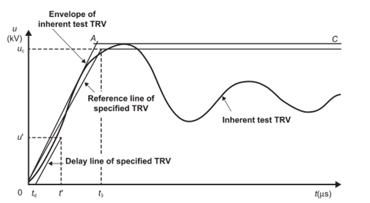
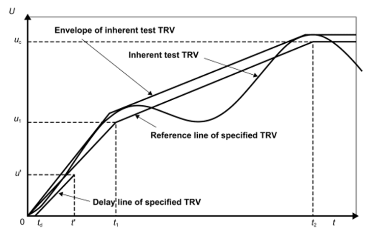
The TRV capability envelope is a standardized reference curve used to compare the system TRV duty with the circuit breaker's rated capability. The comparison considers parameters such as peak voltage, time to peak and rate of rise. A circuit-breaker TRV capability is considered adequate when the applicable rated capability envelope remains above the evaluated system TRV envelope for the relevant duty.
For circuit breakers rated 100 kV and above, the original study basis distinguishes four-parameter envelopes for higher terminal-fault duties and two-parameter envelopes for lower duties; for circuit breakers below 100 kV, two-parameter representation is commonly applied. The applicable parameters and test duties must be confirmed against the current standard, breaker rating and project requirements.
Terminal-Fault Test Duties
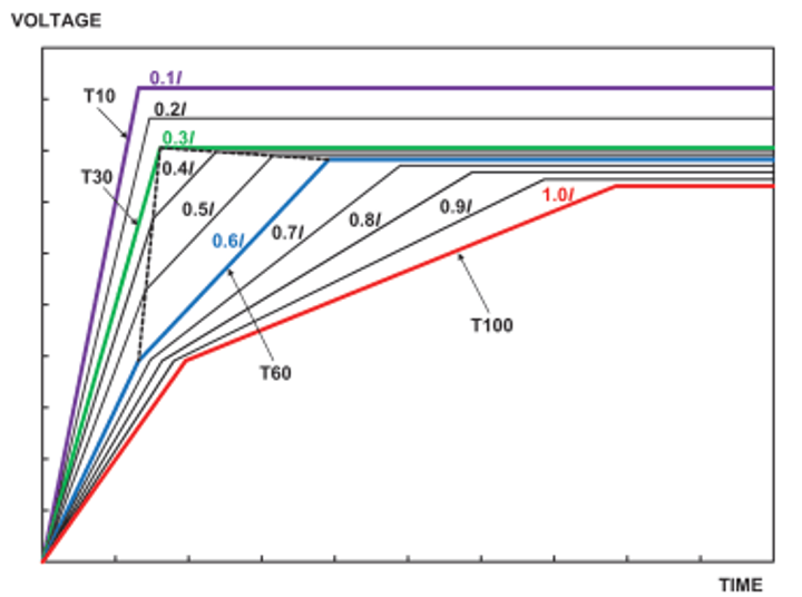
IEEE C37.04 defines circuit-breaker TRV capability in relation to terminal-fault test duties including T10, T30, T60 and T100, corresponding to defined percentages of rated short-circuit interrupting current. These duties are used to establish the relevant capability envelope for comparison with the system response.
TRV Study Methodology
A robust TRV study is built around a representative electromagnetic-transient model of the network and a clearly defined set of breaker duties. A typical workflow is:
Define the study scope, breaker data, network configuration, fault levels and applicable standard or utility requirements.
Develop the power-system model, including relevant sources, transmission lines or cables, transformers, circuit breakers and other network elements that influence the transient response.
Represent relevant electrical parameters such as inductance, capacitance and resistance with sufficient detail for transient analysis.
Simulate the fault and switching conditions required by the study, including terminal faults and short-line faults where applicable.
Model circuit-breaker interruption at the appropriate natural current zero and record the TRV across the breaker contacts.
Extract peak TRV, RRRV, time-to-peak and other parameters required for the selected capability envelope.
Compare the simulated waveform and derived envelope with the applicable IEC or IEEE circuit-breaker capability.
Identify the most onerous case, any exceedance or low-margin condition, and the resulting design or mitigation action.
Simulation Tools
Electromagnetic-transient studies may be carried out using tools such as PSCAD, EMTP or PowerFactory, depending on the study objective, model requirements, available data and client or utility practice. The software choice does not replace engineering judgement: model assumptions, parameter quality, breaker representation and interpretation of the resulting waveforms remain fundamental to the assessment.
Fault Conditions Evaluated in a TRV Study
Terminal Faults
A terminal fault is applied at or close to the breaker terminals. These cases are important because they can produce severe recovery-voltage duty, including high peak TRV. The study evaluates the resulting waveform against the capability associated with the relevant terminal-fault duty.
Short-Line Faults
A short-line fault (SLF) occurs a short distance along a transmission line from the circuit breaker. Travelling-wave behaviour on the line can produce a particularly steep recovery-voltage rise, making RRRV a critical consideration. SLF assessment is therefore important where the breaker and connected line configuration create this duty.
Depending on the breaker application and governing requirements, a project-specific study may also need to consider other fault or switching duties. These should be included only where technically applicable rather than added as a generic checklist.
How TRV Study Results Are Evaluated
TRV study results should show more than a waveform plot. For each simulated case, the analysis should identify the relevant peak TRV, RRRV, time-to-peak and the corresponding standard capability envelope. The most severe case is then determined by comparing the calculated system duty with the breaker's rated capability.
A clear results section normally includes TRV-versus-time plots, the applicable two- or four-parameter envelope, a summary of the critical parameters, and an engineering statement identifying whether the duty is within capability or requires further action. Where an exceedance or marginal condition is identified, the report should explain the technical cause and evaluate practical mitigation options.
For a public technical article, SgurrEnergy should only publish numerical results if they are taken from an anonymised, engineer-validated case or from an explicitly labelled representative example. Project values should not be generated solely to create SEO content.
Compliance with Applicable IEC and IEEE Requirements
The simulated TRV duty is compared with the circuit-breaker capability defined by the applicable IEC or IEEE requirements. The assessment should confirm the governing standard, edition or amendment, voltage class, interrupting-current duty and manufacturer data used for the comparison.
IEEE C37.011-2019 provides application guidance for TRV ratings of AC high-voltage circuit breakers above 1000 V, while IEEE C37.04-2018 establishes ratings and requirements for high-voltage circuit breakers and has an active 2025 amendment. IEEE C37.09-2018 covers circuit-breaker test procedures and also has a 2025 amendment. IEC 62271-100 provides the corresponding international requirements for alternating-current circuit breakers. The applicable standard set should be confirmed for each project rather than assumed from a generic article.
TRV Mitigation Options
If the evaluated system TRV exceeds, or is unacceptably close to, the applicable breaker capability, mitigation should be selected on the basis of the dominant transient mechanism and the wider network design. Common approaches include:
| Mitigation approach | Primarily addresses | Engineering consideration |
|---|---|---|
| Surge arresters | Transient overvoltage magnitude | Application, location and protective level must be coordinated with the network and equipment insulation requirements. |
| RC snubber circuits | RRRV and transient oscillation | Component values and placement require system-specific analysis and equipment integration. |
| Controlled switching | Switching transient severity | Effectiveness depends on the switching duty, breaker operating characteristics and control strategy. |
| Higher-capability circuit breaker | Breaker withstand capability | Breaker selection must be verified against the actual system duty and project specification. |
| System configuration changes | Underlying transient characteristics | Line/cable configuration, grounding and other network parameters may alter the TRV duty and must be assessed as a complete system. |
No mitigation measure should be treated as universally applicable. Component ratings, switching duty, protection philosophy, insulation coordination, network grounding and equipment interfaces should be assessed as part of the engineering decision.
Project discussion: Assessing circuit-breaker duty for a new or upgraded grid connection? SgurrEnergy's Grid and Power Systems team supports fault, protection, stability and compliance studies with engineering interpretation linked to design and interconnection decisions.
Related Power System Studies
TRV assessment is closely connected with the wider network studies used to establish fault duty, protection performance and grid-connection requirements. Relevant SgurrEnergy capabilities include:
Grid and Power Systems - Power-system studies covering short circuit, protection, stability, harmonics, grid code and interconnection.
Grid Code Compliance - Compliance studies, requirement mapping, testing support and technical submissions.
Dynamic, Transient Stability and Harmonic Studies - Simulation-based assessment of system response under grid disturbances.
Engineering and Design - Electrical, substation, secondary-system and interconnection engineering that can act on study findings.
Conclusion
A Transient Recovery Voltage study provides the engineering basis for determining whether a circuit breaker can withstand the recovery-voltage duty imposed by the power system after current interruption. By evaluating peak TRV, RRRV, time-to-peak and the applicable capability envelope across relevant fault conditions, the study identifies critical duties before they translate into equipment or reliability risk.
Where the evaluated duty approaches or exceeds breaker capability, the next step is not a generic mitigation choice but a project-specific engineering assessment of the breaker, network configuration and applicable standards. This is where TRV analysis connects directly with short-circuit, protection, grid-integration and substation design decisions.
Next step: For TRV and related Grid and Power System Studies, discuss the project requirements with SgurrEnergy's technical team.
References
IEC 62271-100:2021 + AMD1:2024: High-voltage switchgear and controlgear - Part 100: Alternating-current circuit-breakers. Official source
IEEE C37.011-2019: IEEE Guide for the Application of Transient Recovery Voltage for AC High-Voltage Circuit Breakers with Rated Maximum Voltage above 1000 V. Official source
IEEE C37.04-2018 + IEEE C37.04a-2025: IEEE Standard for Ratings and Requirements for AC High-Voltage Circuit Breakers with Rated Maximum Voltage Above 1000 V, including the 2025 amendment. Official source
IEEE C37.09-2018 + IEEE C37.09a-2025: IEEE Standard Test Procedures for AC High-Voltage Circuit Breakers with Rated Maximum Voltage Above 1000 V, including the 2025 amendment. Official source
J. Lewis Blackburn: Protective Relaying: Principles and Applications, 4th Edition, CRC Press, 2015.
M. S. Naidu and V. Kamaraju: High Voltage Engineering, 6th Edition, McGraw Hill, 2020.
C. L. Wadhwa: Electrical Power Systems, 6th Edition, New Age International, 2021.
Frequently Asked Questions
Transient Recovery Voltage is the voltage that appears across a circuit breaker's contacts immediately after current interruption. The breaker must withstand this recovery voltage while its dielectric strength is rebuilding after arc extinction.
RRRV is the Rate of Rise of Recovery Voltage, commonly expressed in kV/µs. It indicates how rapidly voltage develops across the breaker contacts after interruption. A steep RRRV can challenge the breaker's dielectric recovery and increase the risk of restrike or reignition.
Terminal faults and short-line faults are two important TRV study cases. Terminal faults can produce high peak TRV, while short-line faults can create particularly steep RRRV. The complete case set should be defined from the breaker application and applicable requirements.
The simulated or measured system TRV waveform is compared with the applicable circuit-breaker capability envelope. Peak TRV, RRRV, time-to-peak and the relevant test duty are evaluated to determine whether the system duty remains within the breaker's rated capability.
Potential options include surge arresters, RC snubber circuits, controlled switching, a breaker with higher TRV capability, or appropriate changes to system configuration. The correct measure depends on the cause of the excessive duty and must be validated through engineering analysis.